2N3904 Project • Dec 25, 2025 • Authored by Steve Morrison, BS, Electrical Engineering Technology, MBA
Simple Current Mirror Using Two 2N3904 Transistors
A practical current mirror circuit using two matched 2N3904 transistors to demonstrate how transistor current can be replicated across multiple loads using LEDs.
Introduction
A current mirror is one of those transistor circuits that looks almost too simple to be useful — until you build it and watch it work. With just two matched transistors and a handful of passive components, you can create a circuit where current flowing in one branch is duplicated in another.
In this project, we’ll build a basic BJT current mirror using two 2N3904 transistors. One transistor establishes a reference current, while the second transistor mirrors that current through a set of LEDs. This circuit highlights how transistor matching, temperature, and base-emitter voltage all play a role in real-world electronics.
This is an educational circuit intended to demonstrate transistor behavior rather than deliver precision current regulation.
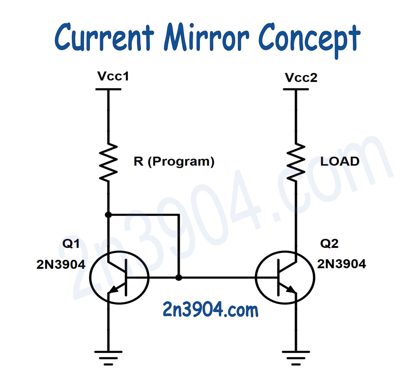
Current Mirror Concept
What You Will Build
You will build a simple current mirror powered from a 9V battery where:
- Recommended bench equipment, parts, basic tools
- One 2N3904 transistor (Q1) sets a reference current
- A second 2N3904 transistor (Q2) mirrors that current
- A resistor and potentiometer allow adjustment of the reference current
- Three LEDs act as visible loads on the mirrored current
Both transistors are physically placed together to keep their temperature as close as possible, improving current matching.
Parts Needed
- 2 × 2N3904 NPN transistors (closely matched)
- 1 × 4.7kΩ resistor
- 1 × 10kΩ potentiometer
- 3 × General-purpose LEDs
- 1 × 9V battery and clip
- Breadboard and jumper wires
Before building the circuit, it is helpful to select two 2N3904 transistors with similar base-emitter voltage using the diode test function on a multimeter. It is also helpful to use a multimeter that has a beta (gain) testing function. This will allow you to better find two 2n3904 transistors that are more closely matched. The more closely matched they are, the better the current mirror circuit will function.
Theory of Operation
A BJT current mirror works by exploiting the relationship between base-emitter voltage and collector current. When two transistors have nearly identical characteristics and share the same base-emitter voltage, they will conduct nearly the same collector current.
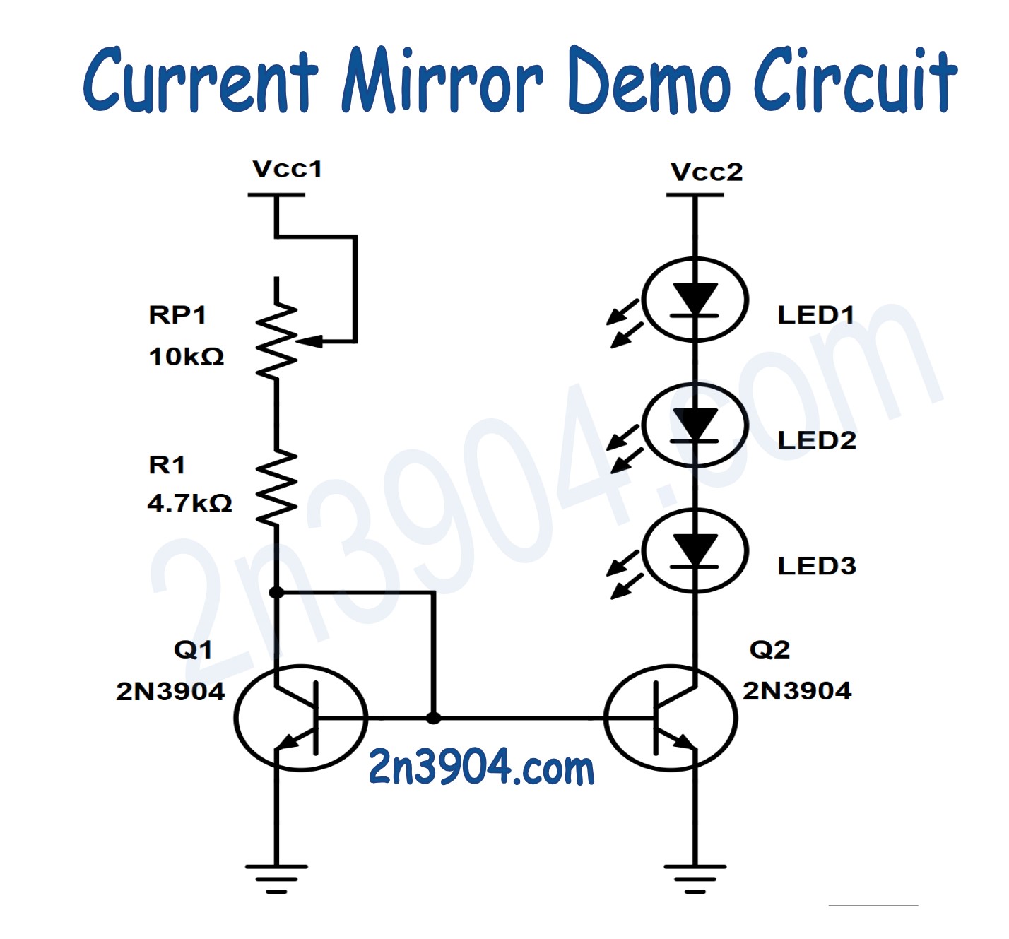
In this circuit, Q1 is configured so that its collector and base are tied together. This forces Q1 to operate in a diode-connected configuration. The current through Q1 is set by the 4.7kΩ resistor and the 10kΩ potentiometer.
Because the base of Q2 is connected to the base of Q1, Q2 sees nearly the same base-emitter voltage. If the transistors are well matched and at the same temperature, Q2 will attempt to conduct the same collector current as Q1.
The LEDs connected to the collector of Q2 provide a visible indication of this mirrored current. As the potentiometer is adjusted, the current through Q1 changes, and Q2 follows along.
Thermal coupling is important. Even small temperature differences can cause noticeable current mismatch due to changes in VBE.
Wiring the Circuit
Wire the circuit as follows:
- Connect the emitters of both 2N3904 transistors directly to ground
- Connect the base of Q1 to its collector
- Connect the base of Q2 to the base of Q1
- Connect the collector of Q1 to the 4.7kΩ resistor
- Connect the other side of the 4.7kΩ resistor to the 10kΩ potentiometer
- Connect the potentiometer to the 9V supply
- Connect three LEDs in series (or parallel, depending on your schematic) to the collector of Q2
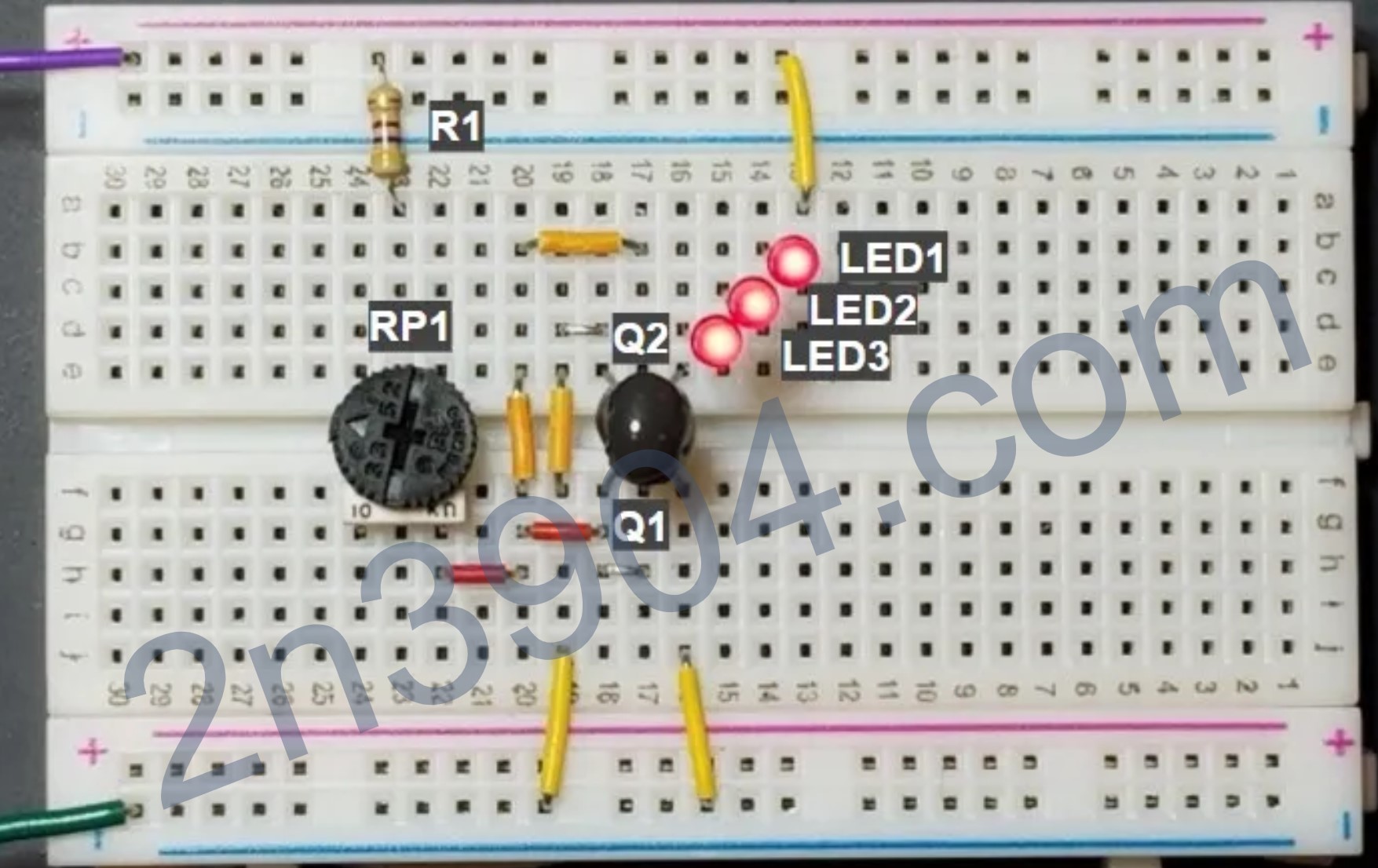
Physically place the two transistors next to each other on the breadboard, and if possible, gently bind them together to ensure they remain at the same temperature.
Schematic
Breadboard Layout
Safety Note
This circuit operates at low voltage and low current, making it suitable for learning and experimentation. Even so, always verify wiring before applying power to avoid damaging components.
This project is intended for educational purposes only. It should not be used in safety-critical, medical, automotive, industrial control, or mission-critical applications.
The current mirror shown here is not temperature-compensated or precision-calibrated. Real-world current regulation requires additional circuitry, protection, and adherence to applicable electrical standards.
Summary
This project explores a basic BJT current mirror built with two 2N3904 transistors, a resistor, and a potentiometer. By matching the transistors and thermally coupling them, a reference current is established and mirrored to drive multiple LEDs with nearly identical current.