2N3904 Project • Dec 26, 2025 • Authored by Steve Morrison, BS, Electrical Engineering Technology, MBA
Building Basic Logic Gates with the 2N3904 Transistor
Learn how simple logic gates work by building an inverter, AND gate, and OR gate using only 2N3904 transistors, resistors, and a 5-volt supply.
Introduction
Digital electronics are built on an idea that is deceptively simple: every signal is either ON or OFF. From that single concept comes everything from calculators to computers. But before logic lived inside tiny integrated circuits, it existed as individual transistors switching currents on and off.
In this project, we strip digital logic down to its bare essentials. Using only 2N3904 transistors, resistors, and a 5-volt power supply, we’ll build three fundamental logic gates: an inverter (NOT), an AND gate, and an OR gate. These gates form the backbone of all digital systems.
Rather than treating logic gates as black boxes, we’ll focus on why they behave the way they do. By pairing each circuit with its truth table, you’ll see how abstract logic rules are enforced by very real electrical behavior.
What You Will Build
- A transistor-based inverter (NOT gate)
- A discrete transistor AND gate
- A discrete transistor OR gate
- Truth table demonstrations for each gate
- A conceptual pathway to NAND and NOR gates
Each gate uses LEDs to represent logic states, making the results visible and intuitive. All circuits operate from a regulated 5 V supply, similar to standard digital logic levels.
Parts Needed
- Recommended bench equipment, parts, basic tools
- 2N3904 NPN transistors
- Current-limiting resistors (470Ω)
- Current-limiting resistors (2.7kΩ)
- LEDs for output indication (optional)
- Momentary switches or jumper wires for inputs (optional)
- 5 V DC power supply
- Breadboard and hookup wire
Understanding Logic and Truth Tables
Logic gates exist to answer yes-or-no questions. In electronics, these answers are represented by voltage levels. A HIGH voltage (near 5 V) represents a logical “1” or TRUE, while a LOW voltage (near 0 V) represents a logical “0” or FALSE.
A truth table is simply a compact way to describe how a logic circuit responds to every possible input combination. It does not describe how the circuit works — only what it does.
The power of truth tables is that they allow us to reason about logic independently of the hardware. Once we understand the logic behavior, we can then look at how transistors are arranged to enforce those rules.
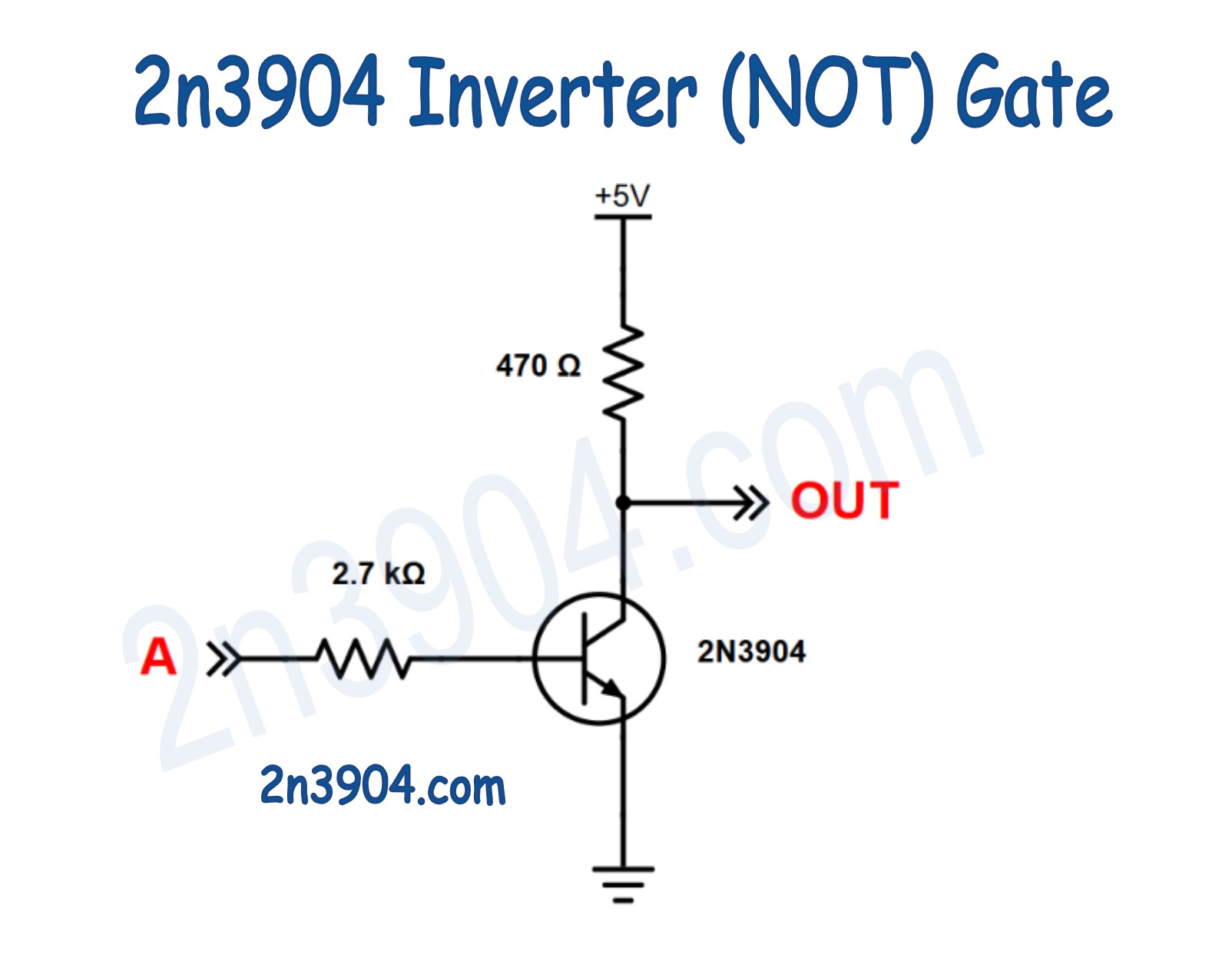
Inverter (NOT Gate)
The inverter is the simplest logic gate and, arguably, the most important. Its job is to reverse a logic signal. If the input is TRUE, the output becomes FALSE. If the input is FALSE, the output becomes TRUE.
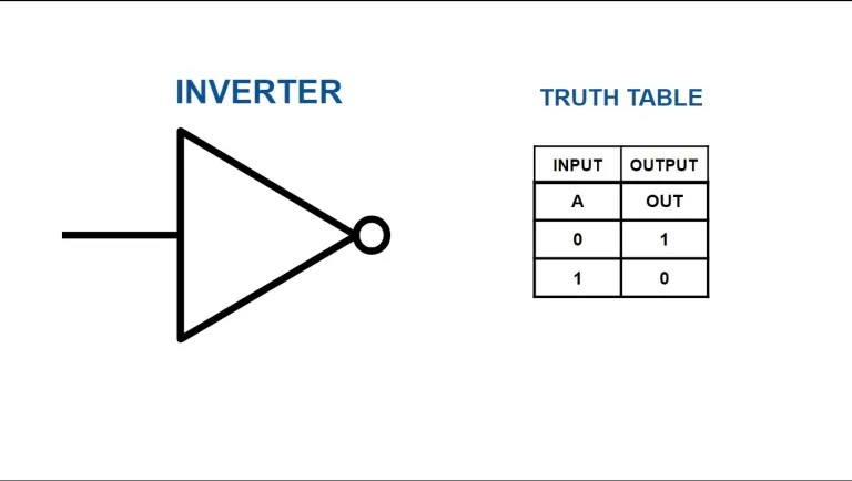
The truth table for an inverter contains only two rows, because there is only one input. This simplicity hides its importance: without inversion, logic would be extremely limited. Inverters allow logic states to be flipped, combined, and rearranged into more complex decision-making systems.
Electrically, the behavior is straightforward. When a HIGH signal is applied to the base, the transistor turns on and pulls the collector toward ground, forcing the output LOW. When the input is LOW, the transistor turns off and the collector resistor pulls the output HIGH.
This circuit highlights a key idea: logic inversion is a natural result of using a transistor as a switch. The inverter becomes the building block that allows AND and OR circuits to be transformed into NAND and NOR gates.
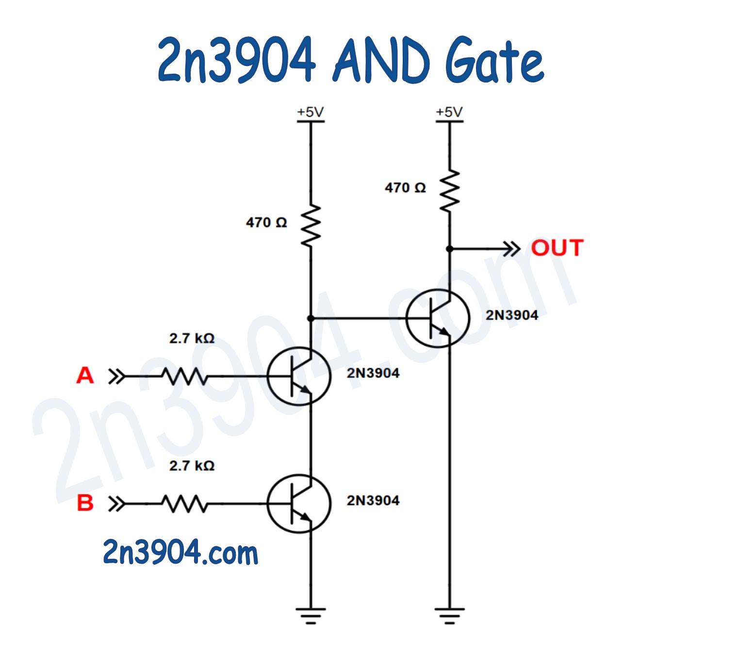
AND Gate
An AND gate answers a very specific question: are both inputs TRUE? Only when the answer is yes does the output go HIGH. Any missing or FALSE input forces the output LOW.
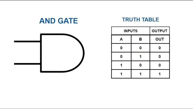
The AND gate truth table clearly shows this behavior. Out of four possible input combinations, only one results in a TRUE output. This makes the AND gate a logical “gatekeeper” — it requires full agreement from all inputs.
From a transistor perspective, this means current must be allowed to flow through multiple stages before the output can activate. If even one transistor is off, the current path is broken and the output remains LOW.
This physical requirement mirrors the logical requirement perfectly. The circuit literally refuses to conduct unless all conditions are met.
By placing an inverter after the AND gate, the logic flips and becomes a NAND gate. This transformation is so powerful that entire digital systems can be built using NAND gates alone.
OR Gate
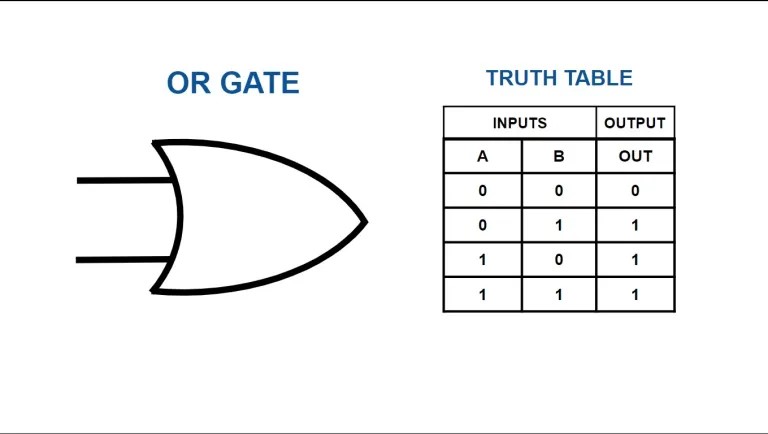
The OR gate answers a different question: is any input TRUE? If at least one input is HIGH, the output goes HIGH. Only when all inputs are FALSE does the output remain LOW.
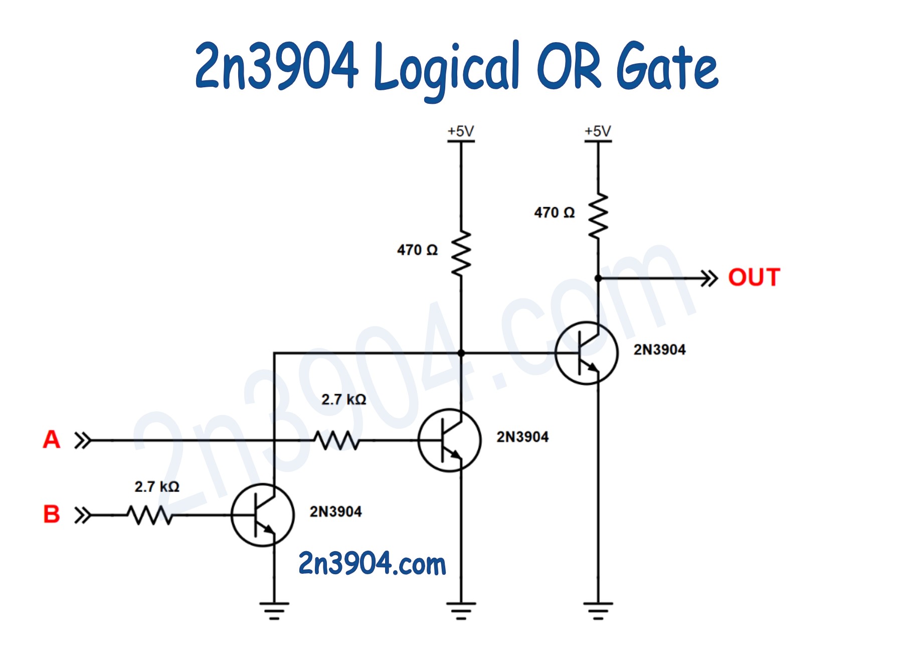
The OR gate truth table shows that three out of four input combinations result in a TRUE output. This makes the OR gate permissive — it allows action as soon as one condition is satisfied.
Electrically, this is implemented by providing multiple current paths to the output. If any input transistor turns on, current flows and activates the output stage.
Once again, the physical circuit enforces the logic rule. The hardware does not “decide” anything — it simply behaves according to the rules imposed by transistor switching.
Adding an inverter after the OR gate produces a NOR gate, which, like NAND, is a universal logic gate capable of implementing any logical function.
Why This Matters
While modern logic circuits use millions or billions of transistors, each one is still performing the same fundamental task demonstrated here: switching current based on conditions.
By building logic gates from discrete transistors, you gain insight into how abstract logic statements are translated into physical systems. This understanding carries forward into microcontrollers, CPUs, PLCs, and digital control systems used throughout electronics and industry.
Safety Note
This project operates at a safe low voltage, but care should still be taken to verify connections before applying power. Incorrect transistor orientation or missing resistors can lead to damaged components or misleading results.
Always use a regulated 5 V supply and avoid connecting these circuits to unknown or unregulated power sources.
Summary
This project demonstrates how basic digital logic can be constructed using discrete 2N3904 transistors. You’ll build a transistor inverter, an AND gate, and an OR gate, explore their truth tables, and see how NAND and NOR gates naturally follow by adding an inverter stage. The goal is not speed or efficiency, but clarity — showing how logic actually works at the transistor level using simple, hands-on circuits powered from 5 V.