2N3904 Project • Dec 24, 2025 • Authored by Steve Morrison, BS, Electrical Engineering Technology, MBA
Astable Multivibrator Using the 2N3904 Transistor
A classic two-transistor astable multivibrator built with 2N3904s. This simple circuit alternately blinks two LEDs and demonstrates how transistors can be used as switches in a free-running oscillator.
The Classic Astable Multivibrator Using the 2N3904
The astable multivibrator is one of the most important transistor circuits you can learn. It is simple, inexpensive, and extremely educational. Despite its simplicity, it demonstrates how transistors behave as switches, how capacitors store and release energy, and how feedback causes a circuit to oscillate without any external input.
In this project, we’ll build a classic two-transistor astable multivibrator using 2N3904 NPN transistors. The circuit alternately flashes two LEDs, creating a free-running oscillator that never settles into a stable state.
What does “astable” mean?
The term astable means “not stable.” In electronics, this refers to a circuit that has no stable resting state. As soon as power is applied, the circuit begins switching between two states on its own.
This is different from other common multivibrator types:
- Monostable – one stable state, one temporary state
- Bistable – two stable states (latches and flip-flops)
An astable multivibrator is always active. There is no trigger, no button, and no control signal. The oscillation is entirely created by the interaction between transistors, resistors, and capacitors.
Parts List
All of the parts for this project are common and inexpensive. Exact values are not critical, but the values listed below produce a comfortable blink rate that is easy to observe.
- Recommended bench equipment, parts, basic tools
- (2) 2N3904 NPN transistors
- (2) LEDs (any color)
- (2) 1 kΩ resistors (LED current limiting)
- (2) 47 kΩ resistors (base bias resistors)
- (2) 10 µF electrolytic capacitors (timing capacitors)
- 5 V to 9 V DC power source
- Breadboard and jumper wires
You can experiment with different resistor and capacitor values later to change the blink rate. Larger capacitors will slow the oscillation; smaller capacitors will speed it up.
Schematic Overview
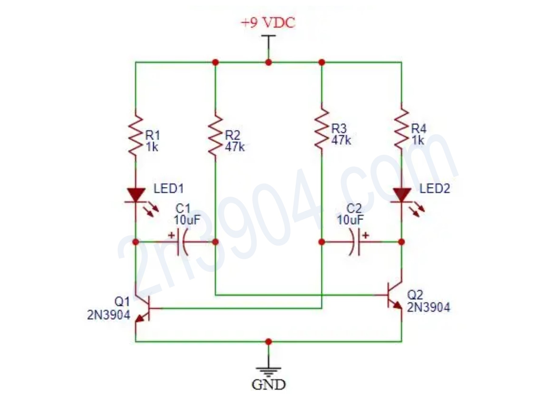
The schematic below shows the complete astable multivibrator circuit. Each transistor is wired as a switch, and the capacitors are cross-coupled between the collector of one transistor and the base of the other.
Theory of Operation
To really understand how this circuit works, it helps to think of the transistors as electronic switches, not amplifiers. Each transistor is either fully off (cutoff) or fully on (saturation). The LEDs make it easy to see which transistor is on at any given time.
When power is first applied, the circuit does not start in a perfectly balanced condition. Due to tiny manufacturing differences, one transistor will always turn on slightly before the other. Let’s assume that transistor Q1 turns on first.
Step-by-step operation
- When Q1 turns on, its collector voltage drops close to ground. Current flows through the LED connected to Q1, causing it to illuminate.
- The sudden drop in Q1’s collector voltage is coupled through a capacitor to the base of Q2. Because the voltage across a capacitor cannot change instantly, this drives Q2’s base negative with respect to its emitter.
- A negative base-to-emitter voltage forces Q2 firmly into cutoff, turning it off. With Q2 off, its LED is dark.
- While Q2 is off, the capacitor connected to its base begins charging through the 47 kΩ resistor. This charging happens slowly and follows an exponential curve.
- Eventually, the voltage on Q2’s base rises to about 0.7 volts relative to its emitter. At this point, Q2 turns on and enters saturation.
- As Q2 turns on, its collector voltage drops, lighting its LED and simultaneously forcing Q1’s base negative through the opposite capacitor.
- Q1 turns off, and the entire process repeats in the opposite direction.
This back-and-forth action continues indefinitely. The frequency of oscillation is determined primarily by the RC time constant formed by the 47 kΩ resistors and the 10 µF capacitors.
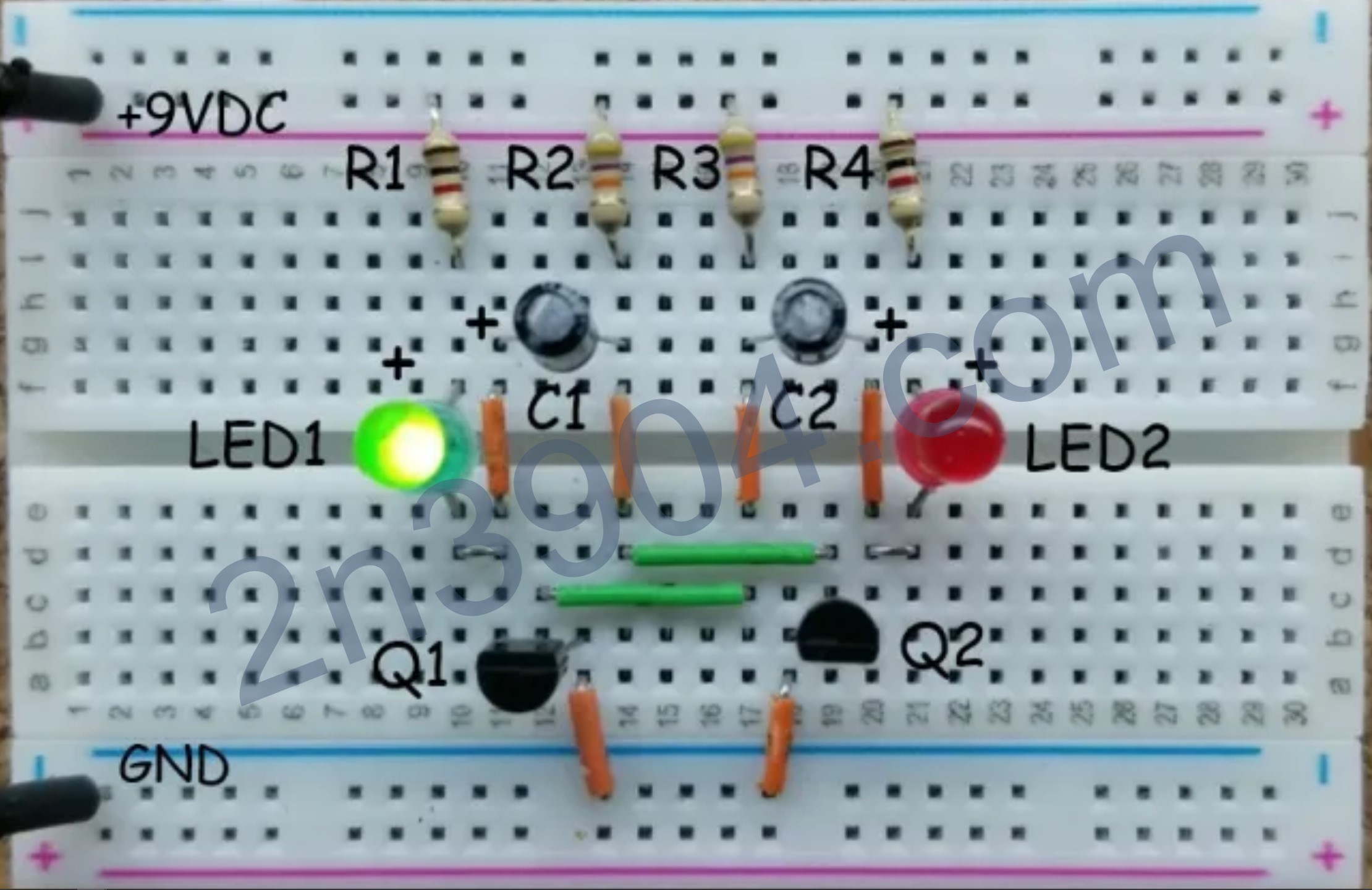
Building the circuit on a breadboard
When assembling this circuit on a breadboard, pay close attention to the pinout of the 2N3904 transistors. With the flat side facing you, the pins are typically arranged as Emitter, Base, and Collector from left to right.
To simplify wiring, one transistor is often rotated 180 degrees so that the collector and base connections line up more cleanly on the breadboard. This is normal and does not affect operation.
Why this circuit is important
The astable multivibrator may look simple, but it teaches several critical concepts that appear again and again in electronics:
- How BJTs behave as saturated switches
- How capacitors store and release energy
- Why feedback causes oscillation
- How RC time constants control timing
- Why clean switching matters in digital and power circuits
Once you understand this circuit, you are well prepared to move on to more advanced projects such as transistor-based logic gates, PWM generators, and improved oscillators with sharper square-wave outputs.
Summary
This astable multivibrator is a foundational 2N3904 project that demonstrates transistor switching, RC timing, and feedback. It’s simple enough to build on a breadboard, yet powerful enough to explain how oscillators, clocks, and timing circuits work in real electronics.