2N3904 Project • Dec 25, 2025 • Authored by Steve Morrison, BS, Electrical Engineering Technology, MBA
Low-Side Relay Driver Using a 2N3904 Transistor
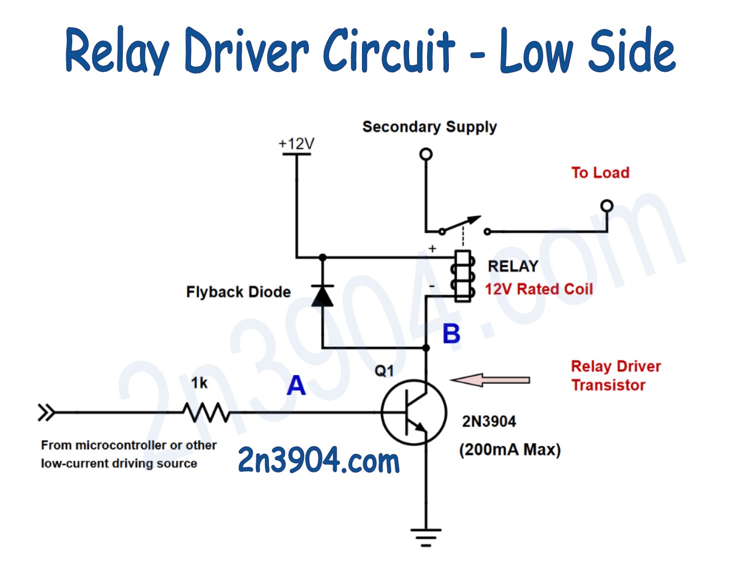
A simple and reliable low-side relay driver circuit using a 2N3904 transistor, flyback diode, and base resistor to safely control a 12V relay from a low-current logic signal.
Introduction
Relays allow low-power electronics to control higher-voltage or higher-current loads, but they cannot be driven directly from a microcontroller pin or logic output. This project demonstrates a classic and extremely reliable solution: a low-side relay driver using a single 2N3904 NPN transistor.
In this circuit, the transistor acts as an electronic switch. A small current applied to the base allows a much larger current to flow through the relay coil, energizing it. A flyback diode is added across the relay coil to protect the transistor from voltage spikes when the relay turns off.
This is one of the most common real-world applications for the 2N3904 and is widely used in microcontroller projects, industrial controls, and automation circuits.
What You Will Build
You will build a low-side relay driver circuit where:
- The emitter of the 2N3904 is tied directly to ground
- The collector switches the low side of a 12V relay coil
- A 1kΩ base resistor limits base current from the control source
- A flyback diode safely clamps inductive voltage spikes
The input signal can come from a microcontroller GPIO pin, logic IC, or any low-current control source capable of supplying a few milliamps.
Parts Needed
- Recommended bench equipment, parts, basic tools
- 1 × 2N3904 NPN transistor
- 1 × 12V relay (coil current within 2N3904 limits)
- 1 × 1kΩ resistor (base resistor)
- 1 × Flyback diode (1N4148 or 1N4001–1N4007)
- 12V DC power supply
- Control signal source (microcontroller pin, logic output, or switch)
- Breadboard and jumper wires
Theory of Operation
The 2N3904 is an NPN bipolar junction transistor. When a small current flows into the base, it allows a much larger current to flow from collector to emitter.
When the control input applies a logic HIGH (typically 3.3V or 5V) through the 1kΩ resistor, base current flows into the transistor. This drives the transistor into saturation, effectively pulling the collector close to ground.
With the collector pulled low, current flows from the 12V supply, through the relay coil, and into the transistor. The relay energizes and its contacts change state.
When the control signal goes LOW, base current stops. The transistor turns off, the collector current ceases, and the relay de-energizes.
Because relay coils are inductive, turning them off causes a high-voltage spike. The flyback diode provides a safe path for this current, protecting the transistor from damage.
Wiring the Circuit
Wire the circuit as follows:
- Connect the emitter of the 2N3904 directly to ground
- Connect one side of the relay coil to +12V
- Connect the other side of the relay coil to the collector
- Place the flyback diode across the relay coil
- Diode cathode to +12V
- Diode anode to the transistor collector
- Connect a 1kΩ resistor from the control signal to the base of the transistor
- Ensure the control source and 12V supply share a common ground
Once wired, applying a logic HIGH to the base resistor will energize the relay.
Schematic
Safety Note
Relays are often used to switch high voltages or mains-powered equipment. Always keep the low-voltage control side electrically isolated from high-voltage loads, and never work on energized circuits.
Ensure the relay coil current does not exceed the maximum collector current rating of the 2N3904. If higher current is required, use a power transistor or logic-level MOSFET instead.
This circuit is intended for educational and experimental use only. It should not be used in safety-critical, life-support, industrial control, automotive, or mission-critical applications where failure could result in injury, damage, or hazardous conditions.
For real-world or production systems, additional protections such as fusing, opto-isolation, transient suppression, redundancy, and compliance with applicable electrical codes and safety standards are required.
Understanding this circuit opens the door to controlling motors, solenoids, lights, and other loads while protecting sensitive logic electronics from high currents and voltage spikes.
Summary
This project demonstrates how to use a 2N3904 NPN transistor as a low-side switch to control a 12V relay from a microcontroller or other low-current source. It explains the purpose of the base resistor, the importance of the flyback diode, and how the transistor safely handles the relay coil current.